Steamboat Emma, review of construction and operation
Emma last had water under her keel 12 years ago. In the summer of 2024, I decided to thoroughly overhaul Emma, take her on a few trips on our Mittelland Canal in summer 2025, and then find a new home for her.
A brief look at Emma’s history: In 1997, I had Peter Wadephul cast Beaumaris components in bronze. I then redrew all the individual parts, making various modifications compared to the original from England, and began machining them. In 1999, Emma’s pressure boiler body came about through a chance meeting of a workshop owner, a stainless steel boiler welder, his boss, and myself as a mechanical engineer and pipe bender. Originally, I had planned to complete the engine and boiler before building the hull. But by chance, a friend discovered Emma’s uniquely beautiful riveted steel hull on the Rhine at the end of 2000, which I ultimately “had” to buy and transport to Berlin. In retrospect, it was relatively quick: from the stripped and reworked steel hull in 2001, a seaworthy boat was created through after-hours work between 2002 and 2003, though still without an engine. In 2005, Emma was able to take to the water under steam for the first time in Berlin-Spandau, right next to “my” BMW Motorcycle Plant.
Over the past few months, I have inspected, maintained, and, where necessary, reworked every part of Emma. Alongside many personal memories, numerous technical reflections on my steamlaunch construction came up, some of which I have noted here and evaluated in hindsight.
Steam Launch Boiler Made of Stainless Steel
In the 1990s, steam launch boilers made of stainless steel were very rare. In England, experiments with stainless steel boilers for steam launches reportedly failed because they were soldered in violation of technical standards. As a result, this material was generally considered unsuitable by my Anglo-Saxon online contacts. In contrast, in the process industry, nothing is conceivable without stainless steel boilers. With proper craftsmanship, this material can also deliver its well-known advantages in steam launch boiler construction.
“Plumber’s nightmare” famously begins at every boiler opening. Here, I’ve had the chance to see the most curious fittings and components made of “beautiful bronze” or even brass. I prefer components with guaranteed properties. Nowadays, you can find them online in a wide variety made of AISI 316/V4A. I seal all inlets and outlets directly at the boiler with three-piece ball valves. The three-piece design offers the tremendous advantage that the entire piping to and from the valve can be removed and reinstalled via the four flange bolts without using “hemp.” Cost-effective stainless steel threaded fittings are typically rated for up to 20 bar or 200°C, so we can safely operate them at 10 bar saturated steam = 180°C. Gas ball valves, for example, made of brass, are often only usable up to 60°C, while simple stainless steel fittings, due to their seals, are limited to 150°C. Therefore, as always, keep your eyes open when buying fittings — a glance at the datasheet is well worth it!
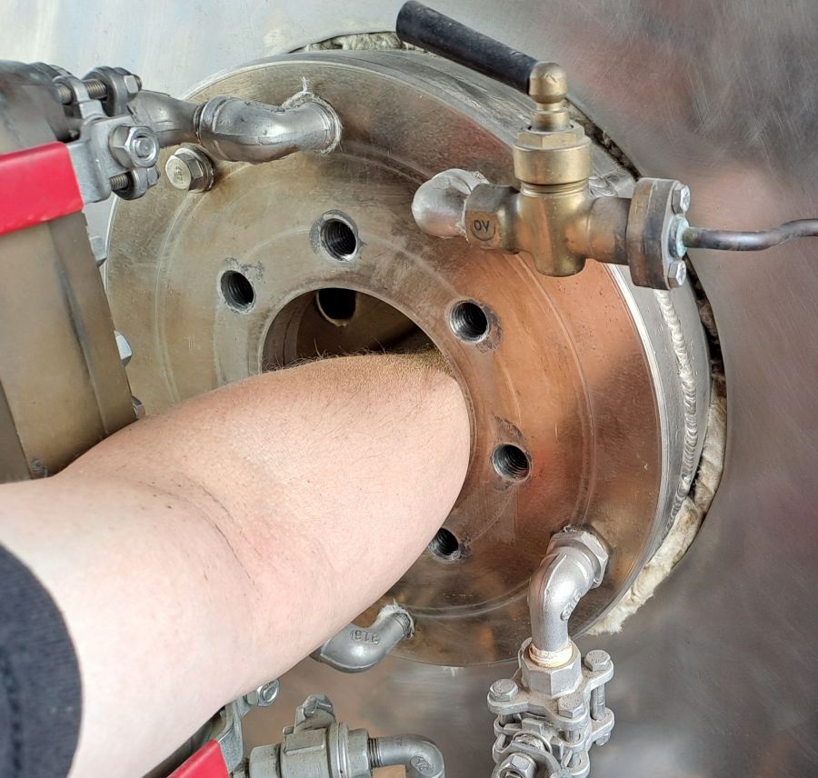
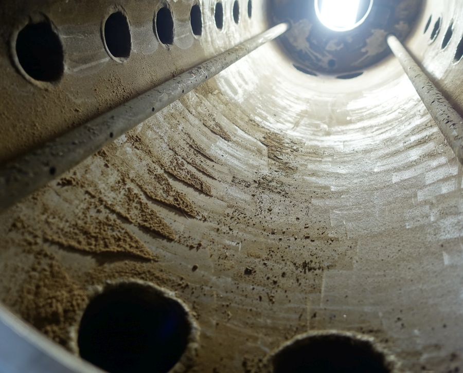
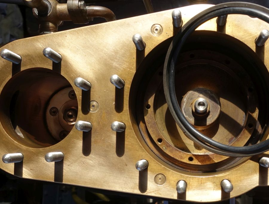
During every boiler inspection, the standard-compliant handholes in the three boiler drums have proven their worth. Working from both sides, I can easily access all areas. The six drum covers are sealed with an embedded O-ring. Over the years, these rings become brittle and need to be replaced. In the attached image, bottom right, you can see the failure of the sealing effect indicated by black deposits and colorful discoloration. Since the flange primarily seals metallically, such a failure during operation poses no significant risk.
The examination of deposits on the drum covers of the upper drum is fascinating. The separation between the water space and steam space is clearly visible. Foam and steam deposit precipitated minerals, as well as oil introduced despite filtration in the hotwell, on all unheated “cold” areas. These include handhole covers and drum covers, as well as the adjacent approximately 80 mm wide zone where the upper drum protrudes through the boiler casing.
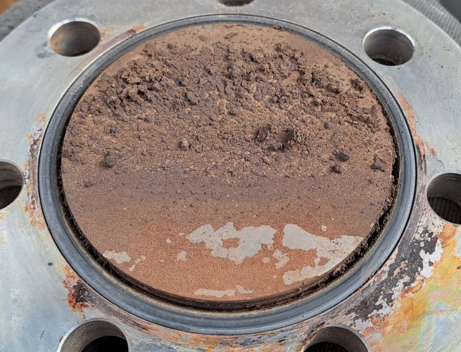
In the lower part of the cover, in the water space, another major advantage of the boiler material becomes apparent. Stainless steel and limescale deposits have such different thermal expansion rates that the “limescale” simply flakes off the smooth VA-material upon cooling. Deposits in the steam space and water space can be wiped off with a cloth and then completely removed with a bit of nitro-thinner.
All heated surfaces showed a very thin, powdery coating on the inside after 5 years of operation. Using a section of a hard plastic school ruler, I could effortlessly “sweep” this coating off the tube surface. The boiler tubes with a 30 mm inner diameter were cleaned as far as possible with a bottle brush.
The two pipes running through the entire upper drum serve the boiler feed through the machine pump and hand pump. The perforations in the pipes are designed to distribute the water evenly into the drum. Feeding into the upper drum results in significantly faster water mixing and prevents “cold feet” compared to feeding into the lower drum. The steam pressure drops immediately upon feeding, not only when water mixing is stimulated by increased steam extraction. The pressure gauge thus reflects the actual boiler condition much more directly.
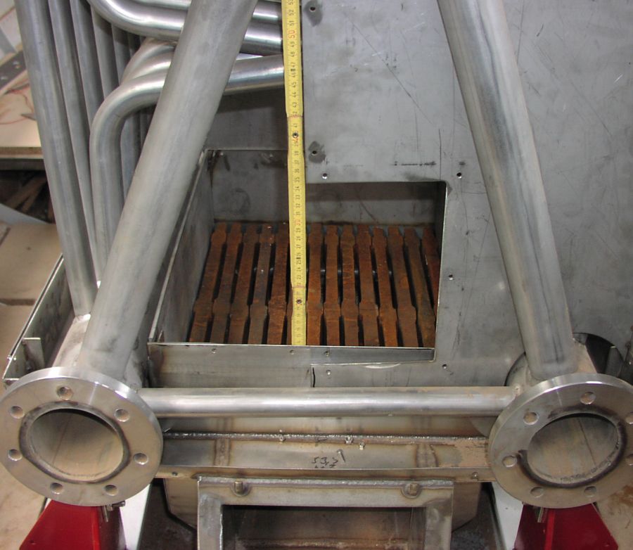
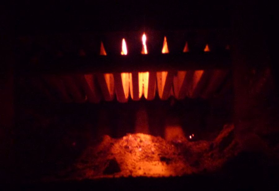
The maintenance-free grate construction has also proven itself exceptionally well. I had grate bars cast from gray cast iron to original dimensions, with an 18 mm web width, 10 mm air gap, and an 80 mm high, cooling, and supporting rib. Fuel, air, and fire cannot be miniaturized, and the grate load in our small boilers is not to be underestimated. With a grate weight of 60 kg, I will likely never need the spare grate bars I ordered as a precaution.
Link to more about Emmas steam boat boiler
Engine System
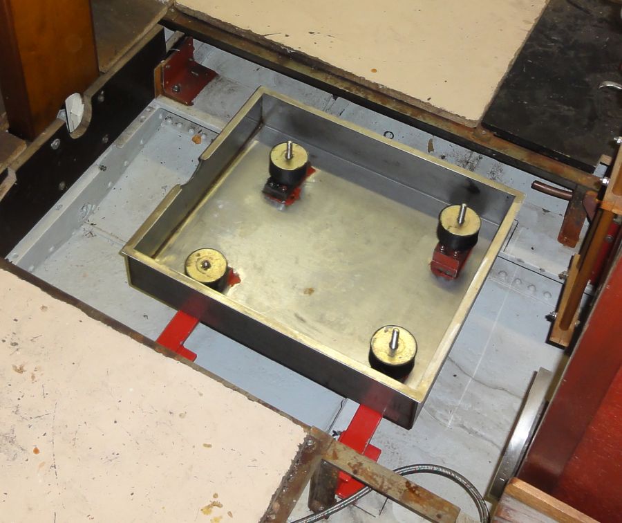
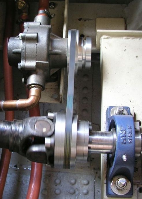
The crankshaft of a marine steam engine was originally aligned in a straight line with the propeller shaft and “rigidly” connected. Those who build their own hull can successfully replicate this, even on our small scale, through clever shaft positioning. Had I implemented this on Emma, a third of the beautiful engine would have been hidden below the deck. All maintenance work would have to be carried out lying down in cramped conditions. Therefore, I decided to raise the lower edge of the engine foundation to deck level using a universal joint shaft. As a further deviation from the original, the engine sits in its oil pan on four robust vibration dampers. This takes vibrations from the steel hull, provides some compensation for the irregular torque of the two-cylinder engine on the drive shaft, and offers protection against hard impacts if a foreign object is struck by the propeller.
Link to more about the engine construction
This mounting method requires that all engine supply and discharge lines can compensate for occurring vibrations. Boiler feedwater and condenser cooling can be implemented using “garden hoses” and armored hoses from the plumbing sector. Special care must be taken with the steam supply line. As early as 1999, I was impressed at a steam launch meeting in the USA by the fact that the marine steam engines displayed on land were supplied via long steam hoses from a large boiler. Nowadays, such hoses and matching couplings are available at reasonable prices in our region as well. The Semperit DS 1 Ultra steam hose is available at schlauch-profi.de with a 13 mm inner diameter for €28 per meter and with a 19 mm inner diameter for €38 per meter. It is rated for saturated steam up to 210 °C (peak load 230 °C). A QR code printed on the hose provides the user with a product description and, additionally, a steam table.
The appropriate hose fitting is designed as a clamp coupling. Clearly visible in the photo: The coupling mechanically engages over the collar of the corresponding hose nipple, which is available with internal and external threads. This ensures that the clamp cannot slip off the nipple and that each groove in the clamp aligns precisely behind a ridge on the hose nipple, optimizing the clamping pressure on the hose. As with all stainless steel screws, an anti-seize stainless steel assembly paste must be applied before installation — otherwise, a cutting disc will be needed later.
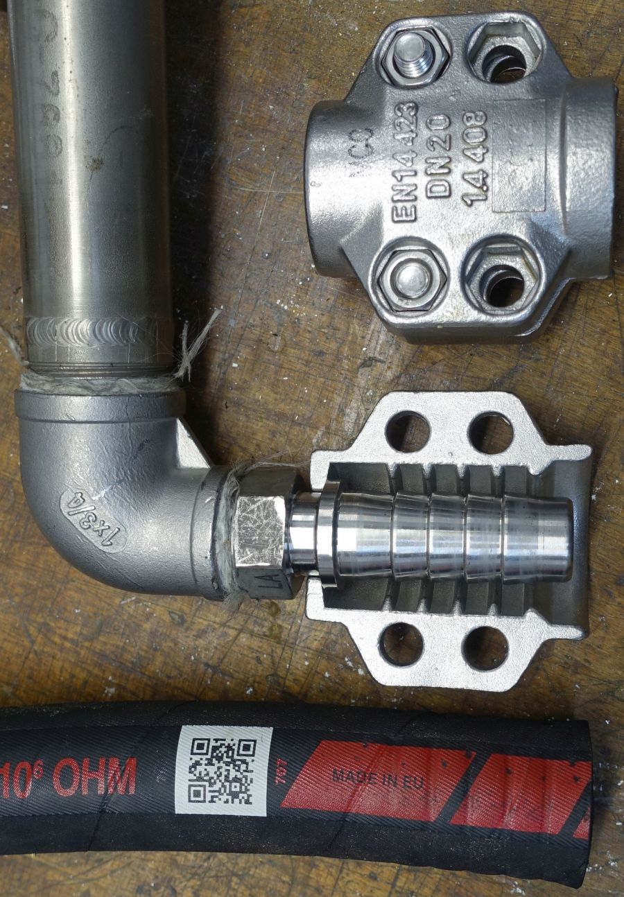
Emma’s first steam hose was custom-made with pressed fittings at a hydraulic specialist shop. Using off-the-shelf hose and clamp couplings offers much greater flexibility. The hose can be cut to size directly on the boat after mounting the hose nipples on the boiler and engine. To precisely cut the fine stainless steel mesh vulcanized into the hose, I use a thin stainless steel disc on a cutting tool. The hose can be slid onto the nipples following its natural curvature, and when mounting the clamp coupling, there is no risk of twisting or loosening adjacent fittings in any way.
As a precaution, I replace the hose every five years. Since the fittings are not subject to wear, such a replacement is cost-effective and can be carried out anywhere without external assistance. In my opinion, such a steam hose significantly contributes to the operational safety of a steam launch. Even if everything is seemingly rigidly fixed in the boat’s hull, road transport, the differing hull flexing on the trailer and in the water, the boat’s movement in the water, and ultimately every propeller rotation create relative movement between the boiler and the engine. It is well known that fatigue fracture is the primary cause of component failure in mechanical engineering. Rigid piping must be executed with great care, and the materials used must be carefully selected. A steam hose bypasses this issue.
Operating Pressure
Before building Emma, I rode along on countless steam launches for study purposes. I often observed how, at locks and docks, precious steam escaped from the safety valves at 8 or 10 bar. So why not simply increase the operating pressure? Decision made, especially since the design of our steam boilers is influenced not only by operating pressure but also significantly by minimum material thicknesses and wear allowances. However, no fittings were available for the design pressure of 16 bar, so I reduced it to 14 bar, approximately 200 °C. I was proud that nothing would escape so quickly on my boat. Yet, practice brought me back to reality. If an inexperienced stoker lets the pressure rise to the maximum at the lock, strong throttling is required for slow starting. This causes extreme flash evaporation behind the control valve, along with the associated steam drying. My minimally lubricated engine immediately responded with unbearable squeaking. Ultimately, I reset the safety valves to 10 bar.
Piston Rings, Flat Slide Valve
Since our boats are stationary more often than they are in motion, I was determined to have my engine made from bronze. To maintain the necessary hardness gradient between the cylinder wall and the piston ring, only plastic piston rings were suitable. These are commercially available, for example, from companies like OMK, Freudenberg, or TESKO. I chose rings made of PTFE-bronze with an embedded O-ring as a pressing spring element. They are installed in the high-pressure and low-pressure cylinders as well as in the wet vacuum pump. The O-rings become brittle over time, while the piston rings themselves experience very little wear. In industrial applications, the closed rings are stretched over the piston during installation and pressed back into their original shape in the piston groove. A non-destructive inspection or replacement of the O-rings is then only feasible for professionals. This issue can be bypassed by designing the piston in two parts. After removing the piston cover, the piston can remain on the piston rod and in the cylinder for ring inspection.
I crafted the piston valve entirely from aluminum and, for simplicity, equipped it only with grooves for sealing through flow turbulence. Any leakages are at least converted into power in the low-pressure cylinder. Here, simplicity took precedence over efficiency.
For the low-pressure flat slide valve, I initially couldn’t come up with a creative solution, so a solid bronze clamshell valve operated on a bronze valve face. During a winter engine overhaul, I fitted the valve face with a hardened and ground tool steel plate. The valve was surface-milled flat and significantly lightened through targeted material removal, reducing its moving mass.
With this piston ring design and the specified maximum 10 bar saturated steam, Emma’s engine operates with a very small amount of lubrication. At the start of a trip and every hour thereafter, I add a few drops of high-temperature steam oil to the HD piston valve housing. This is generally sufficient.
Inboard Condenser
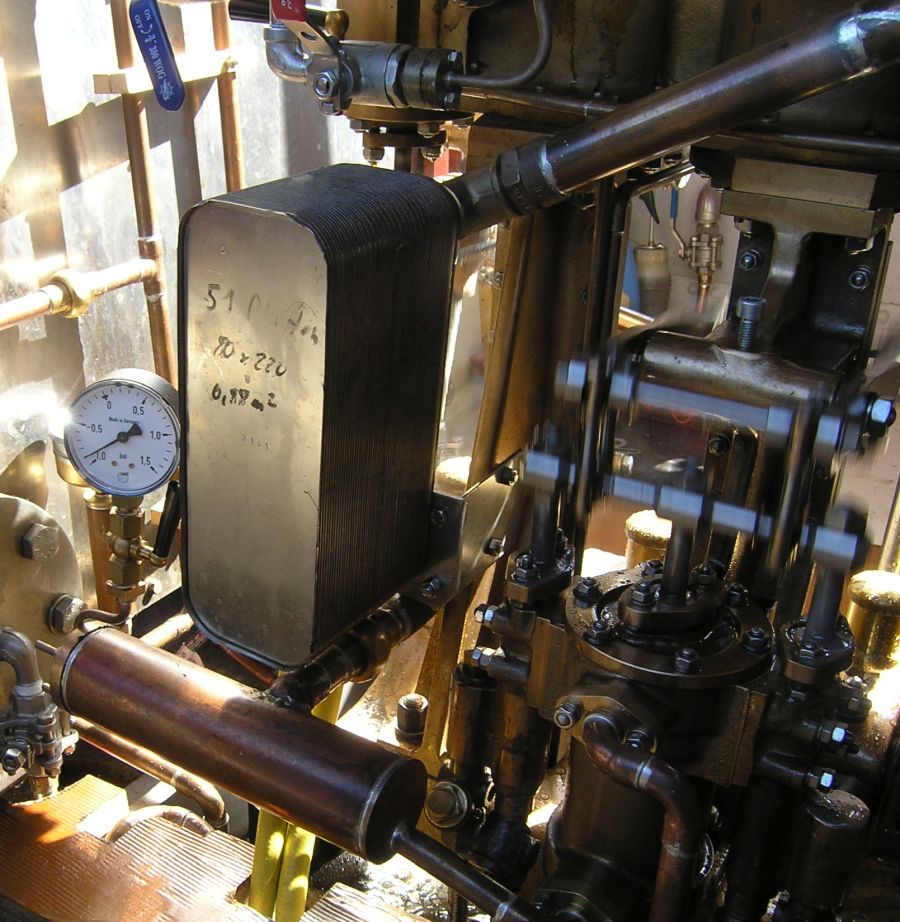
A good, continuous vacuum can reduce steam consumption or significantly increase the engine’s performance. When building Emma, I lacked any information on required condensation surfaces. An outboard condenser must be optimally adapted to the hull shape to offer minimal exposure to water, debris, ground contact, or damage during trailering. Adjustments, maintenance, or repairs are only possible on land. The wet vacuum pump must either be mounted low in the hull or draw water from greater depths, both of which are not always easy to achieve. Therefore, I opted for an inboard condenser.
The steam travels a short, low-loss path from the low-pressure cylinder through an uninsulated Ø 28 mm exhaust line with a slope to the condenser, which is mounted directly on the high-pressure engine frame. The condenser consists of 51 plates, each measuring 70 x 220 mm. The condensate drains from the bottom of the condenser into a transversely mounted, flanged Ø 54 mm collector. From there, the condensate flows with a slope to the vacuum pump at the low-pressure frame. The condensate is then discharged from the pump through a Ø 15 mm copper line to the hotwell. Two garden hoses provide the necessary cooling water flow.
This simply designed and effective condensate system comes with a rather complex cooling water supply. The central component is the cooling water pump. On large ships, these are driven by piston pumps coupled to the engine or by separately installed, steam-powered centrifugal pumps. I opted for a below-deck roller pump, driven by a V-belt from the propeller shaft. These are highly robust, operable in both directions of rotation, and significantly more durable than pumps with rubber impellers.
Initially, I implemented a “steamship-style” cooling water outlet above the waterline. To address the issue of changing pump direction when reversing, I planned to use four check valves arranged like diodes in a bridge rectifier. This worked until, mid-journey on the Spree, a valve jammed after reversing, causing a water short-circuit. Due to the very small volume in the exhaust line, the engine cannot exhale in such a case and stops immediately. During that same trip, I removed all valves and rerouted the cooling water outlet below the waterline using a hose — later, of course, via a proper outboard fitting. When the engine reverses, water is simply drawn from the other side. Beyond improving operational safety, this has the advantage that the water filters are automatically backflushed in the opposite direction with each reversal. To still have some fun with water, I added a hose connection to the cooling water system, allowing warm cooling water to be drawn off as needed for scrubbing the roof, deck, or my body.
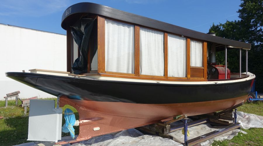
Boat Construction
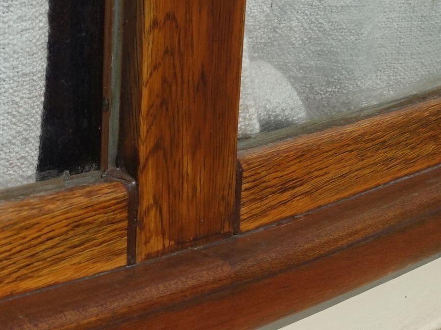
Working with a lathe and milling machine, you're used to precision in the 1/10th of a mm range and better. When I first started working on the woodwork for Emma, it was a big change for me. Even the big growth and shrinkage of aluminum is significantly different than the changes in wood over the course of the year. As a middle ground between these extremes, I built Emma's structure using epoxy-bonded slat construction. Each support between the windows is constructed from at least four individual oak slats. The roof ribs were formed from alternating layers of oak and mahogany slats, glued to a bending jig using the 'Bremen bacon rind' design. The roof edge was made from several layers of mahogany plywood, for which the coaming of the steel hull provided the shaping base. Emma still owes this construction today, as her structure has survived many years of sun and snow without warping.
Like a wooden window on a house, I treated Emma with an open-pore, UV-protective wood stain every five years. I only use products from the construction chemicals sector, as this sector has a much larger research budget than products from the 'paddleboat department'. For aesthetic reasons, I had painstakingly finished the roof edge with a glossy, transparent 2K wood varnish. It looked great at first. During the many lock trips in and around Berlin, slight contact between the roof edge and the lock wall was unavoidable. Water quickly penetrated these damaged areas and caused the varnish to flake off in blistering formations. I spent two winters touching it up. For a utility boat like Emma, that seemed too much effort, so today an open-pore wood varnish does an excellent job here too.
Link to more about the cabin construction
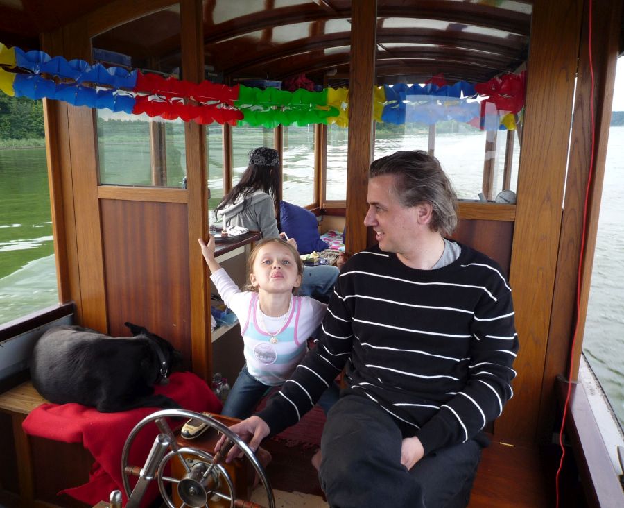
“Driver’s Workstation”
There are probably three basic configurations for the 'driver's workplace'. Sitting on the starboard side with the helm in front of you is, of course, the classic English approach. Those living on a body of water with no current might be able to argue this with docking facing the direction of travel. I think having the helm on the ' starboard side for right-hand drivers' (= port) is a better option. However, if the driver wants to eat something or relax, they have to swap places. If there's something to be checked or greased on that side of the engine, they have to stop. Docking on the starboard side is rather difficult to do alone. That's why I placed the helm in the center of Emma, behind the engine. This position provides complete flexibility in all the situations described above and doesn't make just one person the main player on board – I still remember a picture joke in a US magazine: 'I built a steam boat that can be operated by one person, I just haven't found that person yet.